
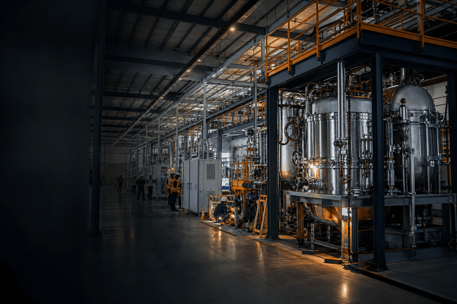
What project owners need to know.
Czochralski silicon is pulled under a flowing inert atmosphere, conventionally argon, held at reduced pressure by a continuously running vacuum system. The gas is not a background condition: it carries away silicon monoxide evaporating from the melt before that SiO can reach the graphite hot zone and return as carbon monoxide, and the pressure and flow it is held at directly shape the oxygen and carbon a crystal inherits. Purity is specified against public guides — SEMI PV6 for bulk argon in photovoltaic applications and SEMI C57 for semiconductor grades. Because argon is consumed continuously across a furnace fleet, on-site supply and recovery are planned alongside the equipment rather than after it, and in India that planning is now visibly happening at the point where solar cell and semiconductor plants are being built.
The atmosphere is process equipment, not a utility
Gas and vacuum are usually the last items on a crystal growth project plan and the first ones to be value-engineered. That ordering is backwards. The Czochralski method grows silicon in an inert atmosphere, commonly argon, inside a sealed chamber held below atmospheric pressure, and the condition of that atmosphere is one of the levers that decides what the crystal comes out as. A furnace fed marginal gas through a marginal vacuum envelope does not fail loudly. It quietly produces material at the edge of specification, and the cause is usually looked for everywhere except the utility line.
The practical consequence is a sequencing rule. Gas purity, delivery pressure, flow control, pumping capacity and leak-tightness belong in the equipment specification alongside the hot zone and the puller, and they need to be settled before the furnace order is placed rather than negotiated with a gas supplier afterwards. A plant that fixes its process recipe first and its atmosphere second has already given away a variable it will spend years trying to recover.
- Treat argon quality, flow control and vacuum performance as furnace specification items, not site services
- Fix delivery pressure, purity and redundancy before the equipment order, not after commissioning
- Instrument the atmosphere so that a drift can be seen in data rather than inferred from crystal quality
- Write gas and vacuum availability into the same uptime commitment as the furnace itself
What the argon flow is actually doing
Silicon is melted in a fused quartz crucible, and the crucible wall dissolves into the melt. PVEducation notes that quartz crucibles used in the manufacture of CZ substrates incorporate oxygen into the silicon ingot at parts-per-million levels, on the order of 10^18 cm^-3, and that this oxygen forms complexes with boron doping that degrade carrier lifetime. Most of the oxygen that enters the melt leaves again as silicon monoxide evaporating from the free surface. The argon stream flowing over that surface is what removes it.
If the SiO is not carried out of the chamber, it meets the graphite parts of the hot zone and reacts, producing carbon monoxide that can diffuse back to the melt and load the crystal with carbon. That loop — crucible to melt, melt to SiO, SiO to graphite, graphite to CO, CO back to melt — is the mechanism behind most of the oxygen and carbon behaviour a grower spends time fighting, and the gas flow field is the main tool available for interrupting it. Published simulation work on CZ growth models the furnace under argon at reduced pressure; one 2024 study in Heliyon on oxygen transport works at an argon pressure of 15 Torr with a volumetric flow of 50 L/s, and finds that crucible rotation, not temperature alone, carries a significant part of the oxygen concentration near the crucible wall.
None of this reduces to a single recommended flow rate or pressure. The optimum depends on the hot zone geometry, the gas guide, the crucible and the crystal size, which is exactly why it is a design question rather than a setting to be copied from another plant.
- The argon stream exists to evacuate SiO before it can reach graphite and return as CO
- Pressure and flow are coupled: both shape the transport of oxygen and carbon, and neither can be set alone
- Gas guide and hot zone geometry determine what flow actually reaches the melt surface
- Expect to tune the atmosphere as part of process qualification, not to inherit numbers from a supplier default
Purity, delivery and the specification layer
Argon purity has public reference points, and they should be used. SEMI PV6 is a guide for bulk argon used in photovoltaic applications; it gives maximum impurity levels for the product as supplied at an agreed delivery point, with quality determined in the gaseous phase regardless of the phase in which it was delivered. SEMI C57 provides specifications for the grades of argon used in the semiconductor industry. Referencing one of these in a supply agreement converts a vague expectation of high purity into a testable requirement with a defined delivery point.
The delivery point matters as much as the grade. A guide that governs the product as supplied does not govern what arrives at the furnace inlet after the line, the filters, the valves and the flow controllers. Contamination picked up in distribution — moisture from an imperfectly dried line, air ingress at a fitting, back-diffusion through a poor seal — is a plant problem, not a supplier problem, and it is only detectable if point-of-use monitoring exists. Specify the grade, then specify separately what is measured at the furnace and how often.
Nitrogen, oxygen, moisture, hydrocarbons and carbon oxides are the impurities worth arguing about. The same trace species that a recovery system is designed to strip out are the ones that matter in incoming gas, which is a useful reminder of where the risk sits.
- Name SEMI PV6 or SEMI C57 in the supply agreement rather than describing purity in adjectives
- Distinguish the contractual delivery point from the furnace inlet, and monitor both
- Specify moisture, oxygen and nitrogen limits explicitly; they are the usual route to a silent contamination problem
- Agree the analytical method and the sampling frequency at the same time as the limits
Vacuum integrity, leak-tightness and uptime
The vacuum side of the system does two jobs at once. It establishes the reduced pressure the process runs at, and it continuously removes the gas load — argon plus everything the process adds to it. Leybold, among others, markets a dedicated product range for solar crystal pulling and growing, spanning oil-sealed rotary vane and dry screw pumps, which is a reasonable indication that the duty is treated as an application in its own right rather than as generic pumping.
The duty is dusty. SiO condenses and deposits along the exhaust path, and a pumping arrangement that has not been designed for particulate loading turns into a maintenance schedule nobody planned for. The failure mode is usually not a stopped pump but a slow loss of pumping speed and a slow drift in chamber pressure, which reads at the furnace as a process problem and gets diagnosed as one. Filtration, trapping, cleaning access and spares availability are the difference between a fleet that holds pressure and a fleet that limps.
Leak-tightness deserves the same discipline. A chamber that leaks air into a low-pressure argon environment is admitting nitrogen, oxygen and moisture directly into the growth environment, defeating whatever was paid for in gas purity. Base pressure, rate-of-rise and helium leak testing should be part of acceptance and part of periodic maintenance, with the acceptance thresholds written into the equipment contract rather than assumed.
- Design the pumping path for SiO deposition: filtration, trapping and cleaning access, not just capacity
- Put base pressure and rate-of-rise acceptance criteria into the equipment contract with the test method named
- Re-test leak-tightness periodically; a slow leak imitates a process drift and gets misdiagnosed as one
- Plan pump maintenance intervals and critical spares against the furnace uptime target, not the pump datasheet
Supply and recovery, and what is happening in India
Argon flows continuously for the length of every growth run, across every furnace in the hall. That makes it a genuine operating consumable rather than a one-time fill, and it is why recovery has become standard practice at scale. Commercial pressure-swing-adsorption recovery systems are offered specifically for argon-rich exhaust from silicon monocrystallizers alongside steel-industry sources; Sumitomo Seika publishes a recovery yield of 70 to 80 percent for its PSA systems, with recovered argon at up to 99.999 percent purity, separating argon from nitrogen, carbon monoxide and carbon dioxide by selective adsorption on zeolite. Whether recovery is justified for a given plant depends on fleet size, run profile and local gas logistics, and that is an assessment to run project by project rather than a rule to apply.
In India the gas layer is being built out in step with the cell and semiconductor plants themselves. INOX Air Products' public news record shows an October 2025 investment announcement in Dholera aimed at India's semiconductor industry, a November 2025 partnership for electronic and specialty gas supply to a solar PV cell facility at Dholera, a January 2026 specialty gases contract for a Tirunelveli solar facility, an ultra-high-purity liquid oxygen facility at Hosur commissioned in April 2026 at 6N purity, and a June 2026 fifteen-year contract supplying 2,400 Nm3/hr of ultra-high-purity nitrogen to a 4.5 GW solar plant. Long-tenor on-site supply agreements of this kind are the shape the market is settling into.
That matters for anyone planning ingot or wafer capacity in India, because the policy clock is also running. MNRE's ALMM page carries the amendment to the ALMM order for implementation of ALMM for wafers, updated 17 March 2026, alongside List-I for modules and List-II for cells. A plant that intends to qualify against a domestic-manufacturing framework will be asked to evidence a controlled, repeatable process — and the atmosphere is part of that process. Applicability, timing and grandfathering should be confirmed against the final order for the specific project category.
- Size gas supply against the whole furnace fleet and its run profile, not a single machine
- Evaluate argon recovery on fleet size and local logistics; treat vendor recovery yields as a starting point to verify
- Prefer on-site or pipeline supply where the fleet justifies it, and specify redundancy and backup explicitly
- Keep atmosphere records with the process records; qualification evidence increasingly means the whole envelope
How JRST supports this requirement
JRST supports ingot and wafer projects on the utilities that behave like process equipment: inert gas grade and delivery specification, flow and pressure control, point-of-use purity monitoring, vacuum system scope and acceptance testing, exhaust and SiO handling, argon recovery evaluation, and the sequencing of gas supply contracting against equipment delivery and commissioning. Figures on this page are drawn from public sources and vendor-published material and should be validated for the specific project; final capability, warranty, performance and compliance commitments are defined against the customer's documented requirement.
Discuss your requirement
Mohammed Saif Zaveri connects JRST's industrial content to execution conversations.
As Co-Founder and designated partner of JRST Technology LLP, Mohammed Saif Zaveri works across industrial growth, strategic partnerships, client conversations, equipment strategy, and project pathways for silicon, solar, semiconductor, and advanced-manufacturing opportunities.
This knowledge page is part of JRST's public industrial knowledge base, designed to help buyers move from search terms and early research toward a structured technical-commercial discussion.
View Mohammed Saif Zaveri's profileConnect on LinkedInFrequently asked questions
Why is argon used for silicon crystal growth rather than nitrogen?
Argon is chemically inert toward molten silicon at growth temperature and can be delivered at the purity levels the process needs. Nitrogen is not a neutral substitute in this environment. SEMI publishes dedicated argon documents for exactly this reason: SEMI PV6 as a guide for bulk argon used in photovoltaic applications, and SEMI C57 as a specification covering the grades of argon used in the semiconductor industry.
What does the argon flow actually remove from the furnace?
Principally silicon monoxide evaporating from the melt surface. The fused quartz crucible dissolves into the melt and leaves oxygen behind, which PVEducation describes as entering CZ silicon at around 10^18 cm^-3 and forming lifetime-degrading complexes with boron doping. If the evaporated SiO is not carried out, it reacts with graphite hot zone parts to form carbon monoxide, which can diffuse back to the melt and introduce carbon into the crystal.
What furnace pressure and argon flow should a CZ system run at?
There is no universal answer, and any figure quoted without the hot zone it belongs to is misleading. Published modelling gives an indication of the regime rather than a setting: a 2024 Heliyon study of oxygen transport in CZ growth works at 15 Torr with 50 L/s of argon. The working point depends on hot zone geometry, gas guide design, crucible and crystal size, and is established during process qualification.
How should argon purity be written into a supply contract?
Reference a public standard, name the delivery point, and monitor separately at the furnace. SEMI PV6 gives maximum impurity levels for bulk argon in photovoltaic applications as supplied at an agreed delivery point, with quality determined in the gaseous phase. What arrives at the furnace inlet after the distribution line is a different question, and needs its own point-of-use measurement, limits and sampling frequency.
Is argon recovery worth installing?
It depends on fleet size, run profile and local gas logistics, and it should be assessed project by project. As a reference point, Sumitomo Seika publishes a 70 to 80 percent recovery yield for its PSA systems handling argon-rich gas from sources including silicon monocrystallizers, with recovered argon at up to 99.999 percent purity and nitrogen, carbon monoxide and carbon dioxide removed by selective adsorption. Vendor figures should be verified against the actual exhaust composition.
What vacuum acceptance criteria belong in a furnace contract?
Base pressure, rate-of-rise and a named leak test method, with thresholds and the test procedure written in rather than assumed. The pumping path also needs to be specified for SiO deposition — filtration, trapping, cleaning access and spares — because the common failure is a gradual loss of pumping speed that presents as a process drift, not as a stopped pump.
How can JRST help with the gas and vacuum layer?
JRST works on the atmosphere envelope as part of equipment and plant specification: argon grade and delivery-point definition against public standards, flow and pressure control scope, point-of-use monitoring, vacuum system sizing and acceptance criteria, leak-test regimes, SiO handling in the exhaust path, recovery evaluation, and supplier qualification and contracting for on-site or bulk supply. Final capability, warranty and performance commitments are defined against the customer's documented requirement.
Primary sources and further reading
Last reviewed 2026-09-03. Technical scope, policy eligibility, availability, and commercial terms should be independently confirmed for each project.